


Details of Our Miniature Steam Engine
Click on each picture for a closer look!
.
In this post, we will take a closer look at the details of our new miniature steam engine.
.
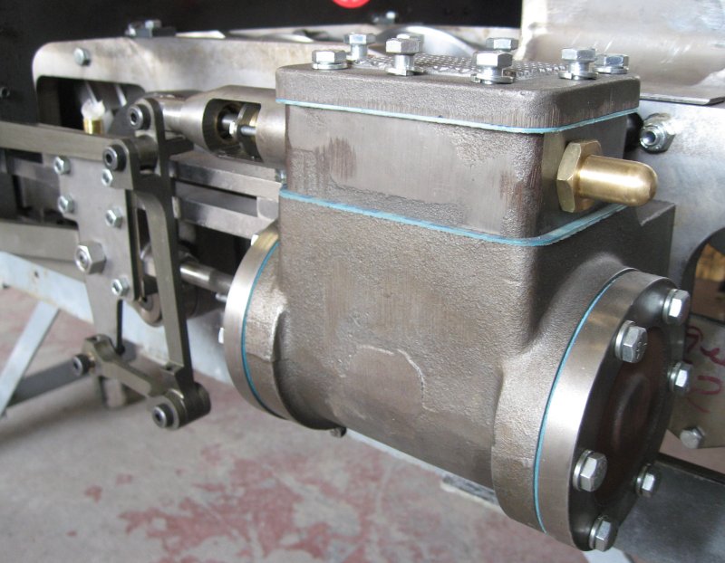 Here we see the steam cylinder assembly in the first picture. Steam at over 100 pounds per square inch (psi) pressure is distributed to each cylinder by the valve in the top of this assembly through the rod at the upper right. The steam then pushes on a piston in the lower part of the assembly which is connected to the drive rod at the lower left which turns the driving wheels.
.
.
.
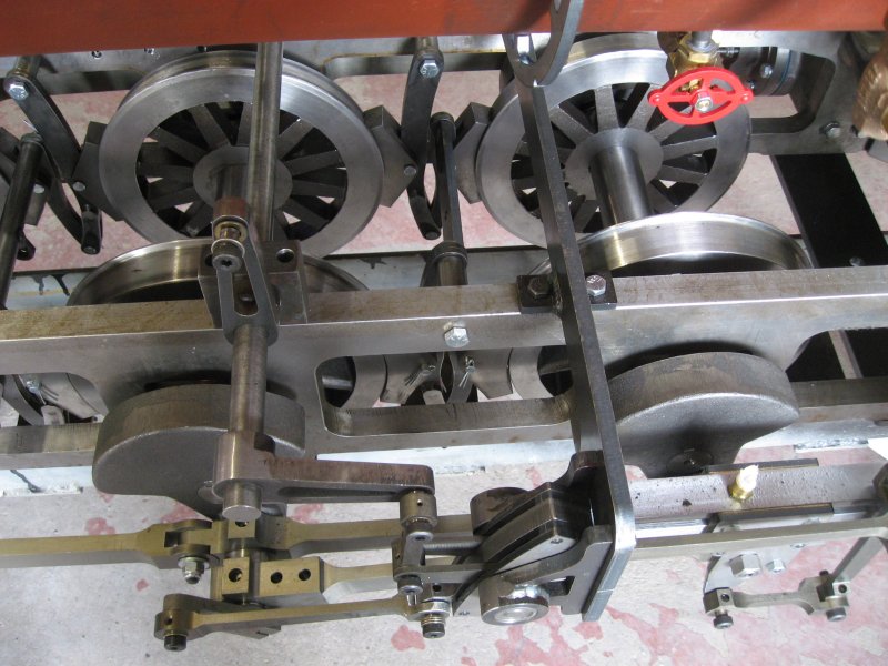 In this picture, we see the chassis and driving wheels. On most steam engines the driving wheels are found on the outside of the frames. But in our engine, they are inside the frames which was commonly done for engines on narrow gauge track, Note the heavy counterweights on the axles. The assembly of linkages in front of the wheels comprise the "valve gear" which are designed to turn the rotary motion of the wheels into just the right movement of the steam valve mentioned early to provide perfect timing for the injection of steam into the cylinders.
.
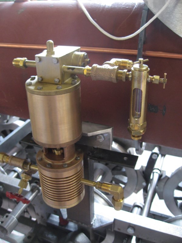 This picture is of the water pump which is used to pump water under pressure into the boiler to maintain an appropriate amount of water in the boiler as it is used up as steam. Steam engines often have as many as three systems to pump water into the boiler: steam driven water pumps, axle driven water pumps and steam-driven injectors.
.
.
.
.
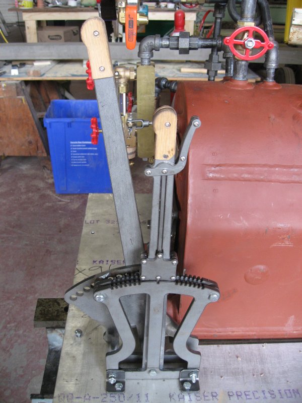 The final picture is of the Johnson bar and brake lever. The smaller lever, the Johnson Bar or Reverser controls the forward and reverse motion of the engine by adjusting the valve gear appropriately. The taller lever controls the braking system for the locomotive.
.
Story and pictures by Russ Milland
<< Home